The STEM Editor allows you to create more than one view of a model, each of which can present a different perspective. A model element can be represented as an icon in several views, and each corresponding icon in the respective views provides access to the
same model data. Each view provides an interface to the same logical model structure. Although model elements are usually created as icons in a view, individual icons can be hidden, or closed altogether, without deleting the logical elements themselves.
When you loaded the localoop model, the STEM Editor automatically opened the Base Stations view. To open another view of the sample model:
- Select Editor from the Results program STEM menu to return to the Editor.
-
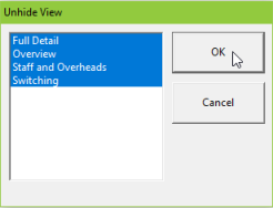
Go to the View menu and select Unhide…. The Unhide View dialog appears, listing all the hidden views of the sample model.
-
Select one (or more) of these views by clicking on its name in the list (<Ctrl> + click for multiple selection), and then click on the OK button. The selected view window (or windows) is displayed. You can move between views by clicking on the View menu and selecting the view of interest from those listed.
The views in the localoop model are described in detail below.
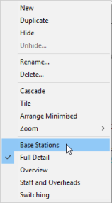
 Base Stations
The busy-hour Erlang traffic generated by residential and business subscribers is combined and used as an input to the Erlang B formula to calculate the number of channels required to meet the busy-hour demand. The Eight channel base stations resources are rolled out on the basis of this calculation and are influenced by the Base Station site plan location element as well. The Base station site resource can accommodate up to five base stations. The backhaul transmission to the switch is performed through the Leased Line resources in the early years, and through a proprietary Microwave System later on. The Network equipment cost trend affects all equipment capital costs in this view.
Switching
The 500-line Switch interface units resources are used to connect subscribers to the switch. The Switch resource has a capacity of 5000 lines, and can be upgraded with 2000-line Switch Upgrades resources. At the top of the view, the dark red line defines the rental and usage tariffs as being identical for the two services. Simply double-click on the line to look at how the Business rental and usage tariffs are related to the Residential tariffs.
Staff and Overheads
You can see how the number of Staff is calculated on the basis of a ratio of 500 lines per staff member. The Minimum No. of Staff location imposes a minimum of 20 people to operate the network. The Admin Building resource is rolled out from the Overhead Driver expression transformation, as can be seen by selecting Input and Transformation from the icon menu. Note how the Output of the Overhead Driver transformation is defined as an if() function, based on the connection demand for Total Connections.
Full Detail
This view shows all the elements in the model. Two new icons are the Single line and Four Line Terminals resources, affected by the Terminal cost trend. Double-click on one of the green lines linking the Residential PSTN service to the Terminals resources to see how the transition from one-line to four-line terminals is modelled. The other new icon is the Minute of Interconnection. This represents one minute of interconnect traffic. Select Costs from the icon menu for the Minute of Interconnection: the interconnect tariff is defined as a Usage Cost, priced at one cent per minute.