The Editor automatically draws lines between icons to indicate relationships between the corresponding elements. You can also add manual links to represent other relationships outside the scope of the model.
 You can use the Connect button on the toolbar to directly define relationships and dependencies between model elements. This button enables you to create a connection between two elements in an intuitive and visual way.
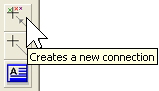
 Click the Connect button. The cursor changes to be as shown.
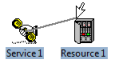
- Click on the first element: it is highlighted, and a connecting line appears which is anchored on that element. As you move the cursor over potential target elements, each of these is also highlighted.
- When the cursor is over the desired target element, click to create the connection.
You can also activate the Connect tool by pressing <Ctrl+Q> or selecting Connect from the Element menu if you find this easier than clicking the toolbar.
By default, the Connect tool requires you to click to select both ends of the connection. If you prefer to select the originating element first, then select Link from Selected Element from the Options menu. Any new connection will immediately originate from the currently selected element.
Connect tool
The Connect tool can be used to define the following relationships:
| From | To | Defines |
| Market Segment | Service |
Service/Customer Base |
| Service or Transformation |
Resource or Function |
Resources Required |
| Resource | Function |
Resource as a member of the Function |
| Resource | Cost Index |
Capital Cost Structure |
| Location or Transformation |
Function, Resource or Erlang Transformation |
Deployment/Sites |
| Transformation | Resource |
Planned Units |
| Resource, Service, or Transformation |
Transformation |
Input |
| Transformation | Market Segment |
Size |
| Transformation | Location |
Sites |
| Transformation | Service |
Customer Base, Penetration or Annual Traffic per Connection
|
| Any element |
Collection or Template |
Element as a member of the Collection or Template |
Figure 1: Using the Connect tool to define relationships
In most cases you can connect either way between the respective icons: the only case where the direction is significant is between a resource and a transformation.
Using the drag and drop technique
The relationships and dependencies between model elements listed in
Figure 1
above can also be defined by Ctrl-dragging between the corresponding icons.
-
Hold down the <Ctrl> key, click on an icon with the left mouse button, and keep the button pressed.
 Drag the mouse cursor to one side. An animated copy of the icon moves off the original.
- Move the animated copy over another icon. Notice that the mouse arrow cursor points down when it is over another icon.
- Release the mouse button to relate the two corresponding elements.
If the two elements are of the same type, you will be presented with the Paste Over dialog with options to copy data from one element to the other, or allow the first to provide default values for the second. For more details see 4.13.3 Finding and removing external links and 4.15 Copying and pasting data.
However, this option is not available for transformations or collections as it is reserved for making connections between such elements.
Connecting to transformations
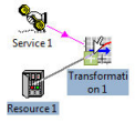
The process for creating a connection to a transformation is simple and intuitive. Suppose you have a default Multiplier transformation
Transformation 1
and you want it to be an Expression transformation taking inputs from both
Service 1
and Resource 1.
-
Create a connection between Service 1 and
Transformation 1.
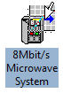
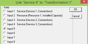
- Click on the Connect button and start making a connection from Resource 1. As the cursor moves over Transformation 1 a
 handle appears at the bottom left of the transformation icon.
-
 If you want to add another input, move the cursor over the handle. The cursor changes to include a + symbol. Click to create the connection. The transformation is automatically changed to an Expression transformation taking its inputs from both Service 1 and Resource 1 .
If you click anywhere else on the icon, the connection to Service 1
is removed and replaced with one to Resource 1. In this case the transformation remains a simple Multiplier transformation with a single input.
Note: If you have actually entered some data for the multiplier input of a Multiplier transformation and then add a connection to another element, the existing Multiplier data will be discarded. STEM will prompt you before making this change.
This functionality makes it straightforward to set up multiple inputs to a transformation, simply by repeatedly dragging onto the
handle. If at some point you want to replace one of the defined inputs, drag from a new element onto the main transformation icon (not onto the handle). A dialog appears showing a summary of all the existing inputs. Click one of these and click OK to replace it with the new element. By default, the new element is added as the next available input.
Connecting multiple elements
Note that the Connect tool will only select one element at a time, and therefore cannot be used to create connections between a multiple selection of elements and a target element. In contrast, the Ctrl drag-and-drop technique can be used to connect a multiple selection of services (or transformations) with a resource to create multiple requirements in one go – thereby saving time when wiring up large models. The same technique can also be used to add multiple items to a collection or template element.
User-defined links
 Manual links can be added to represent other relationships outside the scope of the model. The tool to create a user-defined link between elements operates in a way similar to the Connect tool.
-
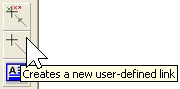
 Click on the button (or press <Ctrl+k> or select Link from the Element menu to activate the Link tool). The cursor changes as shown:
- Click on the first element, then click on the second element. A user-defined link is created.
By default, the user-defined Link tool requires you to click to select both ends of the connection. If you prefer to select the originating element first, then select Link from Selected Element from the Options menu. Any new connection will then originate from the currently selected element.
There are four distinct link types reserved for manual use, initially described as “User 1”, “User 2”, and so on. You can change these descriptions and select the current link type in the Display Options dialog on the Element menu – see 4.18 Formatting a view.
Note: To remove a manual link, right-click on it to display a pop-up menu for the link, and select Unlink.